GRBL Arduino Controller Circuit
Hi, this is my first instructable. I’m trying this out as it goes, so bear with me. I will try to explain as much as I can, but I do not have enough time or resources for visual representations, and on the topic of that I’ll target beginners and intermediate users (like myself) in the field of electrical engineering.
This project focuses on the circuitry and software aspects of a DIY CNC build. Before we begin, I would like to talk about the final product to give you an idea of what to expect from this instructable. Keep in mind that this instructable serves only as a reference and not a full step by step tutorial.
Final Product
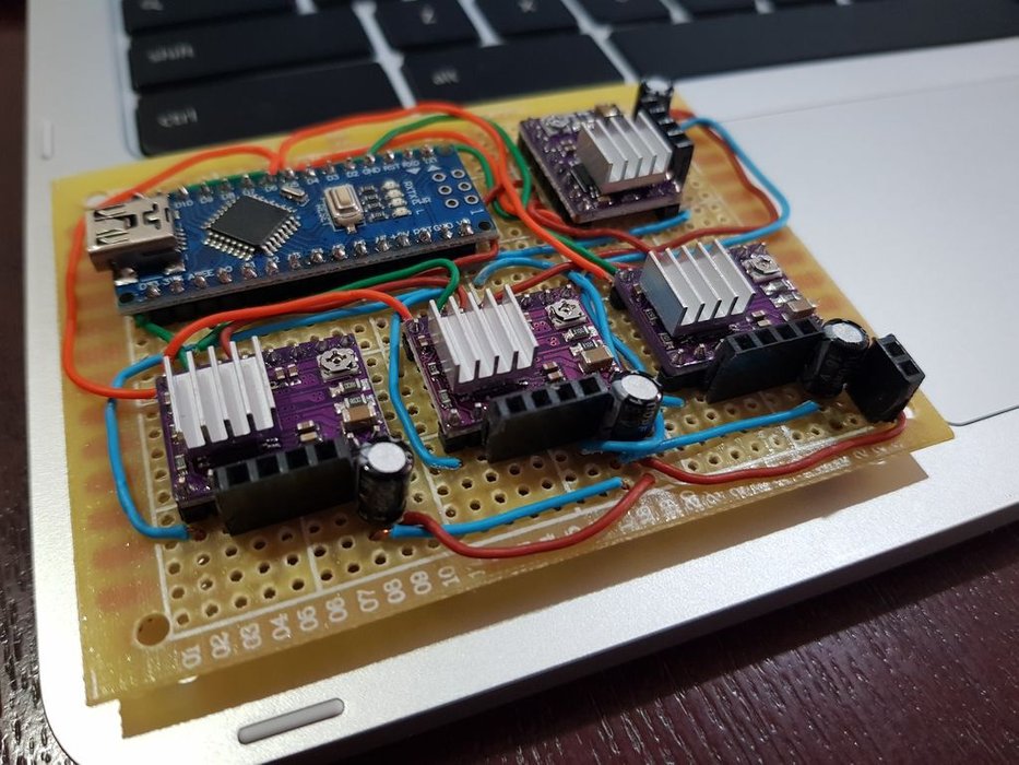
This stepper driver controls 4 stepper motors, 1 on the X-Axis, 2 on the Y-Axis and 1 on the Z-Axis. I used grbl, an Open Source CNC Controller software. It is uploaded onto the arduino once and controlled via a computer (like a raspberry pi). An explanation of grbl and it’s features can be found in grbl’s repo on Github (https://github.com/gnea/grbl).
Onto the technical specs of the stepper driver circuit, it uses Pololu’s DRV8825 Stepper Motor Driver (https://www.pololu.com/product/2133). My 4 steppers are NEMA 17, 12V, ranging from 1A to 2A. The DRV8825 supports from 8.2V to 45V, and a current limit of 2.2A while properly cooled with heat-sinks. The microcontroller is an Arduino Nano. The documentation on grbl displays the pinout of the Arduino Uno, but pinout of the Arduino Nano is slightly different and can be seen here (https://www.instructables.com/id/GRBL-Pinout-Arduino-Nano-v30/).
Prerequisites
Skills: - Some soldering experience - Perseverance, when troubleshooting (it gets pretty bad)
Components or Parts: - 4 Pololu DRV8825 Stepper Motor Driver - 1 Arduino Nano - 4 100uF electrolytic capacitors (I used 16V due to their small form factor, voltage isn’t listed in Pololu’s website hence it may be incorrect) - Wires (I salvaged cat-6a ethernet cables I had laying around) - Prototyping board - (Optional) Some female header pins for connecting the steppers - (Optional) Heat-sinks for DRV8825
Equipment: - Soldering iron and solder - Wire clippers
Note: With some effort you can make this work with other devices such as the more popular A4988 Stepper Driver and other Arduinos such as the Arduino Mega.
Getting Components Ready
We have to get our components ready for assembly. First, solder the necessary header pins into the individual boards. Since I ordered the DRV8825 Driver with soldered on header pins, I only had to solder the arduino nano’s pin headers.
Secondly, after getting the header pins into place, position all the components on the prototyping board. I visualized all the components and how they were going to be wired up, before setting them down. This helps me during the assembly process since it reduces the wire routing needed to be done to connect the drivers to the arduino. I will talk about the wiring process in the following step.
Wiring the Components
This step is where things start to get messy. I will split this process up into 2 parts.
1. Setting up the DRV8825 Driver only
2. Setting up of the 4 drivers and arduino
DRV8825 Connection
Most of the information here can be taken from Pololu’s description on the driver. I’ll list the general steps to take for one driver, and you can then replicate it for the remaining 3 drivers using the same instructions.
Firstly, we have to attach a 100uF capacitor at the VMOT and GND of the driver. Ensure that the capacitor’s polarity is correct, and that + is connected to VMOT while - is connected to GND. The capacitor prevents the driver from getting damaged by LC voltage spikes.
Secondly, we short the RESET and SLEEP pins on the driver with the Arduino’s 5V, and connect the driver’s GND pin to the Arduino’s GND. Careful as there are 2 GND pins on the driver. A schematic of this setup is provided by Pololu on their website.
Thridly, we connect the STEP and DIR pins to their respective axis pins on the Arduino. This may be hard to visualize so let me provide an example. Assuming we are working on the Z-Axis driver, we have to connect the STEP pin on the driver to D4 on the Arduino, which is the Arduino’s Z-Axis STEP pin, and the DIR pin on the driver to D7 on the Arduino, which is the Arduino’s Z-Axis DIR (direction) pin.
Optionally you should connect your female header pins to the stepper pins on the driver (4 pins). You can also solder your stepper wires directly to the board, but it is generally not recommended unless you are certain the direction of the motor is correct (especially since we require further configuration of the 2 motors for the Y-axis).
Finished Board
Now that we have determined the connections necessary, we can solder them. This is an error prone and time consuming process so, try to be patient. I will not touch on details about the wire positions needed to connect the circuit together, since it is unique to your own build.
After soldering all the connections required for the 4 drivers to the arduino, you may optionally want to setup your limit switches on the arduino for “homing” in grbl. It is recommended to follow this step due to it’s benefits, but I will skip this step for now for simplicity sake. More information on wiring limit switches can be found here (https://github.com/gnea/grbl/wiki/Wiring-Limit-Switches). Without limit switches, homing is not possible.
Also you should adjust the current limit potentiometer to prevent damaging your stepper. Instructions are provided in Pololu’s website as usual.
With the connections all done, we can move on to uploading grbl to the Arduino, and testing your controller with the next step.
Upload and Test
This page provides instructions to flash grbl to your arduino (https://github.com/gnea/grbl/wiki/Flashing-Grbl-to-an-Arduino). After flashing, you should be able to send commands to your Arduino via Arduino IDE serial monitor. I recommend getting a GUI capable for sending GCodes to grbl. A list of such applications can be found on grbl’s wiki (https://github.com/gnea/grbl/wiki).
Now you can connect your stepper motor to your grbl driver and test each motor before connecting all of them.
An important note for the special 2 stepper Y-Axis, you have to ensure that both the motors travel in the same direction. Your 2 Y-Axis drivers’s STEP and DIR should be cloned from the same arduino pin. You can swap the wire pairs on the stepper to in turn (see what I did there), change the direction of a motor so that both are traveling in the same direction. You can skip this note if you do not have 2 steppers for an axis.
Test your CNC by using the GUI to “jog” an axis, you should see the motor moving on that axis.
Happy Ending (Hopefully)
Thanks for reading this instructable. Yep, no images, I will be improving this instructable in the future. Keep in mind that this instructable serves only as a reference and not a full step by step tutorial, as you can tell from the links I provided for certain instructions. Feel free to ask any questions and I’ll try my best to answer. Thank you!